When you roll out a new phone system one thing that often gets forgotten until too late is overhead paging. For folks in manufacturing/distribution industries you know that overhead paging is generally a requirement that we can’t get around. And there are way too many paging systems and amplifiers out there which all have different connections with different labels and terrible or non-existent documentation. Plus paging systems are a real set-it-and-forget-it kind of thing, so they’re put in and then run for 20 years without anyone ever touching it, so chances are you won’t find anyone with any first hand knowledge of where things are and why they are connected the way they are.
Thankfully, if you’re just looking for a single zone setup all you really need to do is connect your phone system to the paging amplifier. Now these paging amplifiers rarely look like a stereo amplifier that you’re picturing, they almost never even say the word amplifier on them. And to make things worse, somehow paging systems run in some weird parallel circuit configuration over cat5 wire, so the amplifier outputs to the speakers are rarely easy to identify because they just look like any other network/phone wire.
But going back to basics, here is how the system will need towork:
- your cloud-based phone system talks to an ATA device
- The ATA needs to connect to an intermediary device that tells the ATA that the “phone” is “off-the-hook”, for our purposes this would be the Viking PA-2A
- The Viking PA-2A output connects to your paging Amplifier
- Paging amplifier connects to all paging speakers/horns as it always has
Here is a pretty picture to help you visualize it:
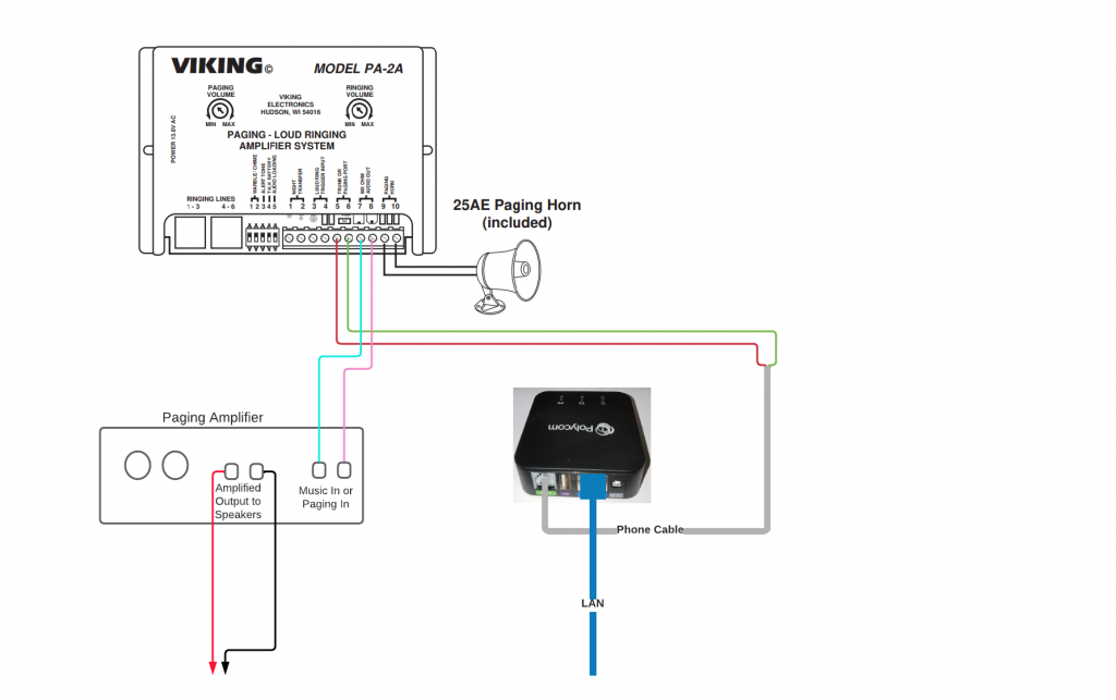
Note: if you have an existing paging system you may have other devices (pagepal, pagepac, transformers, etc.) between your phone system and the amplifier(s). These will likely all need to be removed so everything matches the diagram above. In my experience the pagepal/pagepac thing has the outputs to the amplifiers, so those are the wires you’re going to want to use to hook up to your PA-2A (connections #7 and #8).
These instructions begin at the point where you have already configured/activated/testing the ATA and know you can Page to it (or it can receive phone calls). In our situation, the phone system (8×8.com) expected the paging system to have the phone off the hook when it called. So to test the ATA and the paging configuration I connected a plain old junk analog phone to the ATA, left it off the hook, then dialed the paging extension from a company (8×8.com) phone. Once that worked, I knew the system and that ATA were setup properly.
There are lots of different kinds of ATAs out there but the setup for several types we’ve used (Polycom OBI 300, Cisco SPA 122*, and Cisco SPA 121*).
- Unplug power to any existing Paging Device(s)
- Cut the end off of a standard (RJ11) phone cable, then strip the ends of the Green and Red wires (note: most phone cables today use stranded wires, which are very tiny so be careful and have a spare phone cable on hand before you start in case it takes you a few tries to get it stripped
- Connect the Green and Red wires to the Viking PA-2A (Red to 5, Green to 6)
- Depending what output device you’re connecting the Viking PA-2A to determine what outputs on the Viking PA-2A you’ll want to use:
Connecting to an Existing Paging System:
If you already have a paging system and just need to connect a cloud-based phone system (such as 8×8) to it (using an ATA and the Viking PA-2A) then here is what you’d want to do:
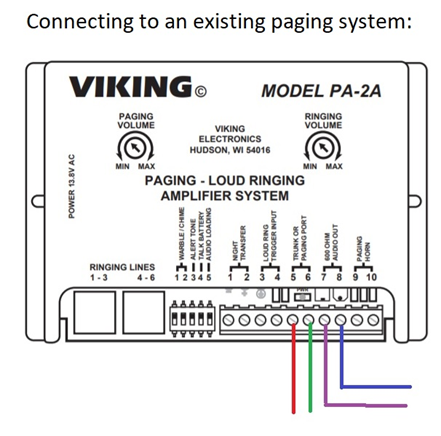
Connect 7 and 8 from the Viking PA-2A (purple and blue lines in the picture above) on the Viking PA-2A to your paging system 600-ohm input (which could be an 3.5mm plug, an RCA connection, or just terminals depending on your amplifier).
Dip switch configurating is going to depend a lot on what you’re connecting the Viking PA-2A to for output. In my situation, here is the Dip Switch configuration:
- Warble/Chime – Off
- Warble/Chime – Off
- Alert Tone – On
- Talk Battery – On
- Audio Loading – Off
- Turn the Paging Volume on the Viking PA-2A to about 25% and turn it up during tests to be safe.
- Connect power to everything, wait several minutes
- Test
Connecting directly to Paging Speakers/Horns:
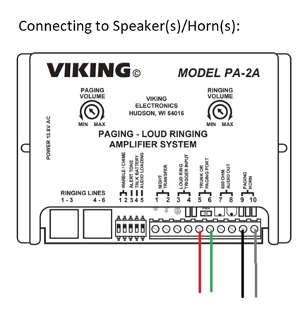
Connect the speaker/horn wires to 9 and 10 on the Viking PA-2A
Dip Switches
here is the Dip Switch configuration if you’re connecting directly to a speaker/horn:
- Warble/Chime – Off
- Warble/Chime – Off
- Alert Tone – Off
- Talk Battery – On
- Audio Loading – On
- Turn the Paging Volume on the Viking PA-2A to about 25% and turn it up during tests to be safe.
- Connect power to everything, wait several minutes
- Test
* Note: For some models of the Cisco SPA required configuration (through the device’s GUI interface) in order for the device to be normally off the hook, with the Polycom OBI unit I did not need to perform any kind of configuration in order for it to be off the hook.
I found the Viking instructions somewhat helpful but I figured a lot of this out through trial and error.
Viking PA-2A Product Manual: https://vikingelectronics.com/wp-content/uploads/documents/product_manual/PA-2A.pdf